|
| Practical Issues in the Development and Implementation of Hyperelastic Models |
|
||
Hubert Lobo and Twylene Bethard, Datapoint Testing Services |
|||
|
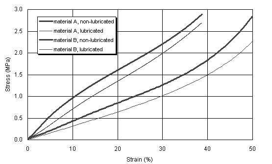
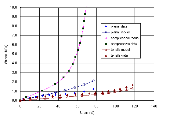
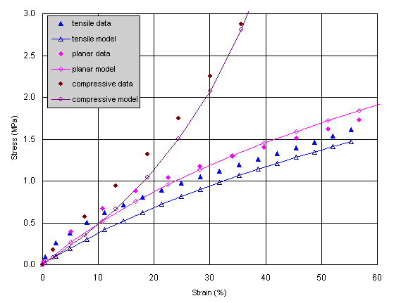
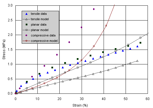
Introduction Hyperelastic models are used extensively in the finite element analysis of rubber and elastomers. These models need to be able to describe elastomeric behavior at large deformations and under different modes of deformation. In order to accomplish this daunting task, material models have been presented that can mathematically describe this behavior [1]. There are several in common use today, notably, the Mooney-Rivlin, Ogden and Arruda Boyce. Each of these has advantages that we will discuss in this article. Further, we will examine the applicability of a particular material model for a given modeling situation. General Model Selection Guidelines The purpose of a material model is to provide the finite element analysis with a description of material behavior that matches the conditions the product sees in real life. This can be a complex matter because the real life scenario may have the product responding simultaneously to a multiplicity of conditions such as rate, temperature and the environment. A classic example may be the rubber boot of an automotive CV joint that is simultaneously seeing large deformation, temperature, cyclic loading and oil or grease. To completely describe the material behavior would require a hyperelastic model on an oil soaked boot rubber over a range of temperatures with some consideration given to rate dependency. It becomes highly impractical to attempt to model all these situations. Accordingly, one often adopts a strategy that seeks to use the simplest acceptable model that achieves a reasonable approximation of the actual scenario. This strategy may be weighted to include a more detailed modeling of the greatest potential sources of failure. Careful thought given to material modeling at the start of the FEA project results in considerable savings in time, money and effort, and will dramatically improve the likelihood of success of the project. Some of these issues are considered below. Mode of Deformation The deformation of rubber and elastomeric materials is very complex. Products often tend to be rather thick so that tension, compression and shear modes of deformation all come into effect. Since the deformation of rubber materials is generally large, and the behavior in each of the above modes is different, we have a somewhat complex problem describing this behavior to the simulation. It is for this reason that the hyperelastic model is the model of choice for rubber. It must be remembered however, that the hyperelastic model, for all its robustness, is not an easy model to come by or to use. Accordingly, it makes sense to examine whether the product under consideration indeed requires such a complex model. In the case of applications where the product is in a relatively simple state of deformation, it may be feasible to achieve a suitable model using just tensile or compressive data. It is important to ensure that there is no artifact present in the measurement. Measurements in more than one mode of deformation should be made equivalent strain rates to ensure that there is no potential of artifact due to rate dependency. It is generally advisable to base measurements on national or international standards, making exceptions to adapt the techniques to the need at hand, in this case, the development of the appropriate hyperelastic model. In the case of tensile tests, non-contact extensometry is needed to ensure that there is no artifact from excessive stretch in the grip region. Video or laser methods are commonly used. Dogbones prevent artifacts from the point of attachment affect the measurements in the gauge region. They become critical when measurements to failure are required, because use of non-contact extensometers obviates the other reason. The planar tension test utilizes a large aspect ratio of width to length. By ensuring that the material contracts only in the thickness direction in response to the applied tensile deformation, it is possible to achieve a state of pure shear at an angle of 45 degrees to the direction of extension. Methods of clamping of the specimen become crucial in the elimination of artifacts, because the gauge region is now so close to the clamps that stress states in the clamped material can easily extend into the gauge region rendering a lower than expected stress-strain response. Again, non-contact extensometry is essential to obtain accurate results. The biaxial tension test is yet another means to provide stress-strain data for a hyperelastic model. Here, the specimen in sheet form is stretched either radially or in the rectangular (x-y) plane achieving a stress state that can prove particularly important in modeling situations where there are large multi-axial strains. There are several important aspects of the test. First, the issue of clamping is fundamental. The x-y techniques require exceedingly complex devices to ensure that clamps separate uniformly from each other as the specimen is deformed. Second, strains must be measured precisely, using non-contact means and far away from the grip sections to prevent artifacts. Cross head separation will not yield displacement data of sufficient accuracy. Such factors contribute significantly to the cost of biaxial data making it useful in situations where the data is essential but not capable of replacing the conventional techniques. Two computer controlled devices are described in [2 & 3]. These devices are excellent for determination of properties in the biaxial stress state to very large stretches. They work well in the prediction of situations such as film manufacture, and stretching where extremely large draw ratios are observed. Bubble inflation presents a simpler experimental approach to achieve the same end. Here, however, the analysis of the resulting data is complex in addition to the test being quite sensitive to parameters such as temperature and uniformity of the film thickness. The technique of Miller [4] has shows an alternate means to radially pull a specially cut circular specimen to achieve an elegant biaxial stress state in the center of the specimen. In their paper, the authors show good correlation between experiment and simulation for the prediction of the biaxial stress state to 70 to 80% strain. They further suggest that the data may be used instead of compressive measurements. The uniaxial compressive measurements are
achieved by means of a standard compression test, eg. ASTM D575 [5] with
the following important exceptions. The test is performed at strain rates
that match those used in the tensile and planar tension tests. Moreover,
contrary to the ASTM requirement that requires a no-slip condition between
the specimen and platens, it is important now to achieve a lubricated
state so as to minimize shear states in the specimen that can occur if
excessive friction exists between the specimen and the platen (Figure
1). Carefully performed lubricated squeezing experiments monitored by
video show that it is possible to achieve fairly large strains with very
little bowing in the specimen. The video experiments also show that the
compressive test is deceptively simple. Reversal of the platens at the
end of a test appears to show that the specimen can undergo buckling behavior
when strained beyond 50%. Accordingly, the issue of equivalency to biaxial
tension needs careful evaluation, particularly at large strains. Of the four techniques described above,
at least two and preferably three modes are needed to develop a good hyperelastic
model. In the selection of tests, careful consideration should be given
to the modes of deformation that will be seen in the product. For situations
where the rubber is being stretched, uniaxially as in the case of retaining
straps and simple drive belts, uniaxial tension data may prove adequate.
For applications where the component is being stretched in two directions,
e.g., a balloon catheter, the data should focus more on the uniaxial tension,
biaxial tension and planar tension modes. The magnitude of deformation
may also dictate the type of test that is needed. In contrast, in applications
where compressive forces are significant such as in gasket and sealing
applications, the uniaxial tension, planar tension and compressive modes
are important. In confined applications, rubber can no longer be assumed
to be incompressible. The determination of volumetric stress-strain data
is important and can seriously impact the simulation. Simplistic measurements
of volumetric compression use a well dimensioned specimen placed within
a piston-cylinder apparatus. Because the hydrostatic stress is so much
greater than the deviatoric stress, the resulting is believed to give
data with little or no artifact [6]. Pressure volume temperature measurements
using a high pressure dilatometer permit the measurement of volumetric
data without this artifact. True bulk modulus measurements are possible
using this technique [7]. Effect of Temperature
References |
|
|