|
| Summer ’96 Volume 2.2 | ||
|
||
|
Technically speaking, there is no such thing as an isotropic material, especially when talking about injection molding of polymers. In a practical sense though, most unreinforced polymers are close enough to isotropic, that for the majority of injection molded parts and their applications, anisotropy is not an issue. The exception worth mentioning is the variation in strain capability of semi-crystalline polymers where, due to molecular alignment, the maximum allowable strain in the direction of flow can be much higher than the strain perpendicular to flow. Problems of anisotropy arise when a glass(or carbon) fiber
reinforced polymer is utilized in a part design. Fiber orientation variations
through the thickness and around the part can produce significant variations
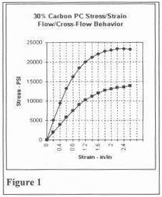
in the mechanical properties. Figure 1 shows how the stress/strain behavior
might vary. A generic example will help to illustrate some of the problems that might arise when trying to analyze anisotropic materials. A cover was analyzed using several different material models to understand what shortcomings each might have. Two different loadings were evaluated to iflustrate first tension / bending loads and then shear loading. The cover is 15 inches long, by 7 inches wide, and 2.5 inches high.
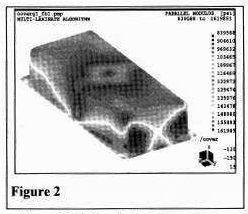
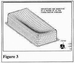
It has a mounting flange around the bottom edge and the cover is center gated. It is molded from a 30%GF PEI. The two loadings were a 5 psi differential pressure (vacuum) with the four corners constrained, and then a twisting load applied at one end with the other end constrained. The first loading was evaluated using the following material models: A isotropic analysis using “datasheet” modulus; Experimental validation of the fiber- orientation codes suggest that Model D should be closest to predicting the correct deflections and stress [1]. The variation of modulus with flow orientation is partially seen in Fig. 2, which plots the predicted modulus parallel to the primary orientation direction, typically parallel to flow. The predicted z-deflections (see Table below) varied over a range of 32% with the orthotropic elastic model (C) corresponding to within 4.5% of the elemental modulus scheme (D). The predicted deflection of the cover using the Model D is shown in Fig 3 The variation in stress however, was even greater. The principal stress predictions for the top (PS2T) and bottom (PS1B) surfaces differed by as much as 57% Surprisingly with Model C, stresses were significantly overpredicted when compared to the other three models. One possible explanation is that the point of measurement of deflection, the center of the cover, is also the gate location, a region of radial flow. This extreme situation with its constantly varying directions may pose a possible limitation to the orthotropic elastic model. To its credit, Model C yields conservative predictions, rendering it safer than the isotropic models A & B In the second simulation, a twist load was analyzed to evaluate what effect orthotropic properties have with shear loads Experimental evidence exists to indicate that the shear modulus is highly dependent on the modulus transverse to the flow direction This load was evaluated using the isotropic analysis (Model A), parallel-to-flow modulus with standard shear modulus formula (Model C), and utilizing orthotropic elemental moduli with two different shear modulus formulae (Model D). The applied torque of 62 in-lb. produced 4.9° of part rotation in the isotropic analysis (A). The orthotropic analysis (C) predicted 5.8° of twist while Model D indicates a twist of 6.8°.
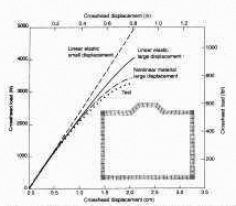
Care should be taken when a fiber filled Manager material is used in a structural application. The best solution to inadequate part stiffness or strength is often NOT to thicken the wallsl Proper engineering analysis of the design before it is “locked-in” can often provide a variety of solutions. Reference - Robert Sherman is Engineering Manager at Bluegrass Plastics Engineenng, Inc. Modeling of plastics for FEA stiffness predictions Plastics are unique materials in terms of their response to stress. With most materials it is common to assume a linear elastic response to stress followed by a break or a region of plastic deformation. Such a simplistic material model can lead to unrealistic predictions in finite element analysis (FEA) of many plastic parts. Plastics have a low elastic modulus, i.e.. a large deformation results from a given applied load. Unlike metals, plastics tend to have a large elastic limit and can undergo large deformations without damage. Finally, the recovery from an applied load may be time dependent (visco-elasfic). The magnitude of these effects varies from resin to resin. However, the following generalizations can be made. In classifying a plastic as brittle or ductile, it can be said that a ductile material exhibits non-linear behavior, particularly at large deformations. It is important to note that the behavior can be non-linear even in the elastic regime. A brittle plastic can be effectively modeled as having a linear elastic response followed by a break. However, many materials in this class fall into the category of filled materials where anisotropy becomes an issue. Here modulus is a function of orientation which, in turn, is determined by the method of production of the part. Isotropic situations Most parts made from unfilled plastics can be modeled effectively using the following scenario. Exceptions that occur when high orientation or large residual stresses are introduced during the manufacturing process will not be covered in this article. Unfilled plastics typically exhibit non linear stress- strain behavior and are best modeled using a multi-linear material model. Here several stress-strain pairs are provided to adequately describe the shape of the stress- strain curve. The FEA program then interpolates between these data as needed. Because of the large strain response to a given stress (low Young’s modulus), linear structural analysis may be inadequate to predict the large displacements that result from an applied load. A geometrically nonlinear large displacement calculation is best suited to such modeling and is quite achievable with modern computers and FEA software (see Fig. 1). By providing realistic predictions, it may actually save time.
The stress strain curves needed to create a good material model require the generation of representative data from a specimen prepared under situations similar to those used for the manufacture of the final part. For example, specimens may be cut from injection molded plaques or from flat sides of blow molded bottles. However, standard ASTM dogbones may also be used. Typical data are generated in tension on a UTM machine using extensometers to measure the elongation. True stress-true strain data are calculated using standard equations. For higher accuracy, extensometers can be placed in the specimen width direction, to measure the actual reduction in cross section as the specimen is elongated. If the predominant mode of deformation is in compression, compressive stress-strain curves must be generated. Finally. it the part will be subject to extreme temperatures. it may be necessary to analyze parts over a range of temperatures. This is because polymers become more ductile at higher temperature and could undergo a ductile- brittle transition at sub-zero temperatures. Anisotropic situations Many engineering resins are filled with glass or carbon fibers to increase the modulus. While this does increase the strength significantly. orientational effects can begin to be significant as the linear fillers align in the flow field which develops during the molding process. Such orientational effects can result in significant differences in modulus measured in, for example, the flow and cross-flow direction of an injectionmolded part. Fortunately, the presence of glass fibers often results in a fairly linear elastic response before failure. In such cases, an orthotropic elastic material model serves as a reasonable model which can be used to model anisotropic situations. The model requires the generation of elastic moduli, E1 and E2, in two principal directions. In the case of injection molding, these could be the flow (0°) and cross flow (90 directions. A Poisson’s ratio (v12) is also needed. Finally, an in-plane shear modulus can be measured using the saddle-shear or rail-shear method. Alternatively, the elastic modulus E45 of a specimen cut in the 450 orientation is measured and G12 calculated assuming the validity of the orthotropic elasticity relationship:
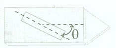
The need to acquire such directional data precludes the use of injection molded ASTM dogbones. Specimens need to be cut from plaques in the specified principal directions (Fig.2). Straight sided specimens are considered adequate because none of the measurements require large deformation of the specimen. Another reason injection molded dogbones may not be used is that the molding process in this configuration creates an anomalously high orientation in the specimen which will overpredict the strength of the part.
The analysis of anisotropic parts also requires a knowledge of the orientation in various locations of the part. It is possible to estimate the orientations in some simple injection molded geometries and in cases of structured composite lay-ups. In more complex situations, such as the injection molding of complex parts, the orientation is determined by the flow direction, geometry and process conditions. In such situations it is necessary to perform a manufacturing simulation to obtain the orientation information. The 1996 Polyflow U.S. Users’ Group meeting, held March 15th in Cleveland, Ohio, highlighted advances in the simulation of polymer processes Talks focused on CAE for extrusion die design, blow molding and film blowing simulation, and on the introduction of kinetic modeling to simulate chemical reaction and foaming. Details will appear in the next issue of Datapoint, which will focus on CFD for process simulation. The Future of Simulation Tools. Computer Aided Engineering in the 21st Century” was the focus of the 7th ANSYS Conference, held in Pittsburgh, May 19 - 22th The four day meeting featured keynote presentations, talks and poster sessions covering applications of CAE to the solution of engineering problems in electronics, automotive, and biomechanics ANSYS announced the availability of the LSDYNA3D solver with its Revision 5 3, slated for release this summer DYNA3D is a FEA code for the solution of dynamic problems, such as impact simulations Hubert Lobo presented a poster, “Improving Solution Accuracy in Plastics FEA Through Better Material Models”. Selected meetings, conferences, and symposia Moldflow User’s Group Meeting, June 17-19, Pittsburgh. ASTM Committee D20, July 22- 25 Salt Lake City, UT. IDES 3 Annual Conference, Aug 1-2, Laramie, WY. ISO TC61, Sept. 21-28, Montreal, Canada C-MOLD User’s Group Meeting. Sept 25-26, Louisville, KY SPE PD3 Regional Technical Conference “Design for the 21° Century”, Oct. 16-18, Boston, MA
The material modeling techniques described above have considerable promise in describing the behavior of plastic parts in FEA analysis. Large deformation theory is needed to simulate the behavior of ductile plastics. Anisotropic plastics may be modeled using a orthotropic elastic theory. as long as the fiber orientations within the part can be defined. References ASTM D5083 94 “Test
Method for Tensile Properties of Reinforced Thermosetting Plastics Using
Straight-Sided Specimens’.
|
|