|
| Fall ’97 Volume 3.3 | ||
|
||
|
New approaches for PVT measurements
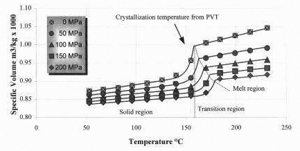
Effect of cooling rate PVT of the injection molded solid The crystalline structure of the solidified polymer in the instrument may differ from that seen in an inlection molded part for several reasons. Phenomena such as shear-induced crystallization and varying crystallinity in the skin-core regions cannot be captured even if it were possible to make PVT measurements at “high” cooling rates. Now, the typical specimen used in the PVT measurements is an injection molded part. This specimen contains the correct morphology (crystal size and composition) of the situation that we seek to simulate. Thus, a series of PVT measurements on such a specimen prior to melting will give us the solid state PVT behavior of the injection molded polymer in the solid state. From these, the PVT characteristics of a polymer under injection molding conditions can be constructed. This technique is highly advantageous in that it captures each of the desired behavioral characteristics needed for the simulation. It preserves all aspects of the current measurement technique, which has been proven to be highly accurate. What changes is the manner in which data are taken and analyzed. This article is based on a presentation made by Hubert Lobo at the Toronto meeting of the CAMPUS/ISO group in April 1997. Additional plots and information from the presentation can be downloaded from www.datapointlabs.com. ISO guide for CAE data: new thermal conductivity ASTM standard approved The ISO TC61 Plastics Committee held its annual September meeting in Davos, Switzerland. A new work item was proposed to set up a design guide specifying the material properties that are needed for the numerous CAE simulation programs in use in the world today. This guideline covers data for structural analysis, injection molding simulation, extrusion simulation, and blow molding simulations. The objective of this document is to set the stage for the generation of these properties by uniform global methods in order to ensure reliable and comparative data. It is hoped that this will greatly enhance the availability of such data in the future. The document was put together by Drs. R. Shastri (USA), G. Dean (UK) and H. Breuer (GER), who would welcome your participation and feedback in the creation of this document. A draft copy can be downloaded from our website (www.datapointlabs.com). The ISO Committed also moved standards for transition temperatures and specific heat to the DIS stage. In other standardization news, ASTM Committee D-20 has approved a new standard testing method, D 5930, for the measurement of thermal conductivity of plastics by the transient line-source technique. This method is designed for testing plastics in the melt and solid state over a wide range of temperatures. The transient method is fast, allowing measurements to be made in materials that might otherwise decompose, and is appropriate for both thermoplastics and thermosets. Datapoint Testing Services performs measurements according to ASTM 0 5930. MFUG presentation notes are now available online Datapoint Testing Services has introduced TestPaks designed specifically tor users of Polydynamics software. The POLYCAD VISCOUS TestPak includes viscosity measurements (both dynamic and capillary, with Bagley and Rabinowitsch corrections), melt state thermal properties, and solid state properties. Viscoelastic effects can also be characterized; call tor details. Clients receive a written report, raw data files, and a data file with model coefficients ready to load into POLYBANK. Polydynamics produces PC-based, user- friendly software for simulation, analysis, design, and troubleshooting of plastics processJ ing operations, including extrusion and film blowing. (www.polydynamics.com) Datapoint Testing Services joins ANSYS solutions partner program Datapoint Testing Services has joined the ANSYS Enhanced Solutions Partner (ESP) program, and is expanding test offerings for structural analysis. ANSYS users will be able order TestPaks that are customized to the particular material model they are using. For details, check the test catalog on our web site: www. datapointlabs.com. Datapoint Testing Services now provides TestPaks for twelve major design analysis packages. TestPaks are sets of ‘ready-to- load’, model-specific material properties tailored to the specifications of the software. Accurate Material data is critical Mold filling simulation software requires an accurate description of material properties in order to solve the physical equations describing the process. The rapid pace of simulation software research and development and the slow pace of standard development cause different laboratories to use different methods for measurement of these properties. This situation can cause problems for simulation software users who are at risk of making wrong decisions based on simulation results that are distorted due to poor material data. This article highlights some of the problems with material properties and gives some tips on how to minimize the risks. Shear Viscosity This property determines the resistance of the material to shear flow, which is the dominant deformation inside the cavity of an injection-molded part. Viscosity is usually measured in a capillary rheometer, where the material is pushed through a capillary at a certain temperature and flow rate and the resulting pressure is measured. The pressure is usually measured above the entrance to the capillary. Since the flow field in the entrance to the capillary involves both shear and extensional deformations, the measured pressure reflects the material resistance to shear and extensional deformations. Using this pressure for shear viscosity calculation will cause over prediction of the shear viscosity since it includes an extensional component. Different techniques have been developed to separate the shear and extensional components to ensure accurate determination of shear viscosity, however the use of uncorrected data is still very common. Usage of uncorrected data can cause over prediction of cavity pressure and clamp force of between 1000 to 30°c, while for fiber filled materials the over prediction can be as high as 50%. No-Flow/Transition Temperature This property is used to determine whether the material is frozen and behaves like a solid, or molten and still flowing. This single value property can dramatically effect mold tilling simulation analysis and its accurate dcterrnination is very important. This property is usually measured by extruding the material through a cooling capillary until flow ceases or with a Differential Scanning Calorimeter. These two measurement techniques can give vastly different results and differences up to 40 C for the same material can be observed. No-Flow/Transition temperature values that are too high will cause over prediction of pressure and, in severe cases, incorrect short shot prediction. Materials with operating melt temperatures that are close to the No-Flow/Transition Temperature, such as Nylon and PBT, are most sensitive to errors in this property measurement. Ejection Temperature This property is used to determine the time at which the part can be ejected, and has great importance in determining the cycle time. Three different measurement techniques are commonly used to measure this property and they can produce vastly different values of up to 50 C for the same material. Two of the techniques, namely the Heat Deflection technique and the Vicat technique, are done in heating, while the determination of the ejection temperature using a Differential Scanning Calorimeter is done in cooling. Values measured by the H.D.T. and Vicat techniques are usually higher than values measured by a DSC and will lead to shorter cooling time prediction. This is especially true for crystalline materials. Thermal Conductivity This property is involved in determination of the material temperature and cooling rate. It is one of the most difficult to measure since polymers usually have very low thermal conductivity values. Three different measurement techniques are commonly iced: hc~t piates hot wire, and coaxial cylinders. The hot plates technique is useful for measurement of thermal conductivity of a solid sample, hence tends to give high values. The hot wire and coaxial cylinders techniques are useful for measurement of the melt and transition stage, hence are more suitable for determination of thermal conductivity for inlection molding simulation. The hot plates technique gives the highest thermal conductivity values while the coaxial cylinders gives the lowest. Differences of up to 100% between the different methods are common. High thermal conductivity values can cause over prediction of the cooling phenomena and pressure. Tips The ultimate solution for material properties measurement for CAE simulation software is standardization. However it is possible to minimize the danger of using wrong material data by following these tips: Always check the material data before running an analysis. Compare the data for the material you are going to use with data of similar materials (i.e. same MEl, same filler content, etc.). Run the analysis with a similar material and compare the results. Try to find out the source of the data and what techniques were used to measure it. Try to follow the project through to verify your simulation against the actual molding. In this way, you can build confidence with the set of data used. In case you have to use a substitute material, use one you have used before on a successful project. Understand the material testing techniques used by the specialist material testing laboratories that provide data for mold filling simulation, and ensure the methodology is suitable for use with your software. Gal Sherbelis is an independent consultant based in Israel, and former Director of Manufacturing Technology at Moldflow. Ply. Ltd. Australia. Interpreting high shear rate predictions in PP hinges P olypropylenes remarkable ability to withstand repeated
flexing makes it the standard material for parts that I have carried out a few experiments over the last few years in several polymers to find a ‘real” limit for shear rates. What I found (working with GE Plastics and Dow Chemicals) were limits based on separation of additives. For instance, I found that shear rates for flame retardant grades of ABS should not exceed 40,000 1/s. At or above this value, the flame retardant packages are released and immediately show up as brown streaks, bloom, etc. As far as PP goes. the only limit I have seen relates to colorant degradation or jetting. This kind of limit in PP should be applied on a grade-by-grade basis due to the wide range of PPs and additive packages. I have yet to see a degradation of mechanical properties of natural materials due to excessive shear rates. I have seen a loss of weld line strength, though, as the additives will surface there more readily. As far as PP goes. the only limit I have seen relates
to colorant degradation or jetting. This kind of limit in PP should
be applied on a grade-by-grade basis due to the wide range of PPs and
additive packages. I have yet to see a degradation of mechanical properties
of natural materials due to excessive shear rates. I have seen a loss
of weld line strength, though, as the additives will surface there more
readily. (T Shear rate numbers in the part can be ignored (except at the gate). 2 Shear stress is only a problem when the flow front is not perpendicular to the hinge.High molecular alignment makes the hinge work, but this
alignment also causes high stress. However, I have seen very high predicted
shear stress and shear rate values and yet the hinge will still pass
thousands of cycles. Heres a tip for hinge design: double gate the part (be
sure to avoid weld line formation in the hinge area) for better control
of the packing and holding phases. This will allow tighter control of
dimensions in the half of the part that would otherwise be filled through
the hinge. © Datapointesting Services (1997) Brand
or product names are trademarks ot their respective owners.
|
|