DatapointLabs launches expansion into new
facility
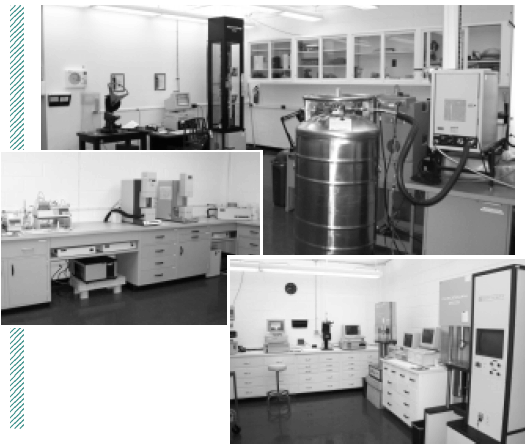 Mechanical, rheological, and thermal
analysis laboratories in the new facility (clockwise from top)
Mechanical, rheological, and thermal
analysis laboratories in the new facility (clockwise from top)
ITHACA, NY: Aug. 27, 2001- DatapointLabs launched an expansion into
a new facility to accommodate its growing line of test instruments.
The new facility is composed of four laboratories. The mechanical
test lab is a new, climate controlled area housing the universal
testing machine, impact testing machines, fatigue and creep machines.
A new rheological test laboratory contains the DMA and capillary
rheometers as well as the thermal conductivity and HDT testers.
The separate thermal analysis laboratory houses a complete Perkin
Elmer suite of differential scanning calorimeter, dynamic mechanical
analyzer, thermo-mechanical analyzer, thermo-gravimetric analyzer,
along with the Karl Fischer moisture analysis equipment. There is
a new machining facility for preparation of test specimens. The
PVT test laboratory remains unchanged and separate from the other
labs.
"Our new facility is 50% larger than our previous space, giving
us room for expansion. And the new labs are attractive, welloganized,
and efficient," says Twylene Bethard, Lab Manager.
No-Flow Temperature in Mold Analysis
The no-flow temperature was first pro posed by Moldflow as a means
to define the temperature where plastic stops flowing in the mold.
This is an important criterion in mold analysis that defines the
location in a mold where the material is solid and unable to flow.
Its proper definition is crucial to determination of flow fronts,
pressure predictions and shear rates. In subsequent implementations
of mold analysis codes, the use of the no-flow temperature was extended
still further as a means to determine whether residual stresses
would accumulate or dissipate at a particular node, the precursor
calculation to the estimation of shrinkage and warpage.
Analysis
The no-flow temperature is based on a simple measure: molten plastic
is cooled at a relatively slow cooling rate in a capillary rheometer
under a constant load. The temperature at which flow ceases is the
no-flow temperature. The technique yields comparable results to
differential scanning calorimetry (DSC) for semi-crystalline materials
(eg. PE, PP, PPS) which undergo a kinetic 'crystallization' transition,
provided that the DSC tests are performed at slow cooling rates.
At the high cooling rates typical to those seen in injection molding,
the transitions observed by DSC occur at significantly lower temperatures
because of super-cooling effects.
In the case of amorphous materials such as PS and PC, the no-flow
temperature is always higher than the typical DSC transition, the
glass transition temperature. Further, it has been observed for
amorphous materials that the 'solidified' material can start flowing
once again if the load is increased. Amorphous transitions do not
depend on cooling rate because the glass transition is not kinetic
but thermodynamic in nature.
Failure to account for these anomalies has resulted in significant
doubt being cast upon the no-flow temperature and the technique
has been the subject of widespread criticism as being subjective
and, at best, suited for comparative purposes only. While it is
true that there could be better ways to measure this transition,
importance of measuring a solidification transition correctly cannot
be understated. Good simulations require a precise solidification
transition.
Several means have been proposed to replace the no-flow temperature.
C-MOLD's transition temperature is based solely on DSC, assigning
the transition using measures taken from ASTM standards. While it
is easy to measure and presents advantages, the DSC transition temperature
suffers from a few drawbacks. Chief among these is the assumption
that the thermal transition observed by the DSC correlates to the
rheological change that results in the cessation of flow in the
mold. It can be seen from Figure 1 that this assumption holds well
for semi-crystalline materials where the transition is rapid once
crystallization commences.
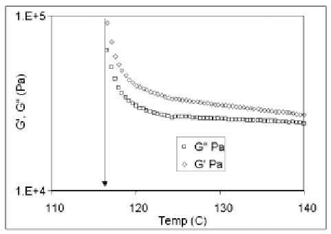 Figure 1. Parallel plate rheology data
for semi-crystalline polypropylene
Figure 1. Parallel plate rheology data
for semi-crystalline polypropylene
In the above experiment, we performed rheological measurements using
a parallel plate rheometer, observing the variation of the two components
of the modulus (G? and G?) with temperature as the sample cooled.
In the melt processing region, viscous effects predominate and the
G? is higher than the elastic component G?. As we lower the temperature,
elastic effects become more important and the melt becomes visco-elastic.
Here the elastic component G? is higher than the viscous component
G?, though both moduli are low enough that flow is possible. Upon
solidification, both moduli increase dramatically, indicating that
further flow is not possible. This dramatic increase in modulus
represents the solidification transition. While the transitions
agree for both techniques, the rheological data is better in that
it pinpoints the degree of crystallinity at which solidification
occurs, rather than assuming that it occurs at onset of the transition.
With amorphous materials, the transition is more gradual (Figure
2) and the no-flow and DSC transition temperature do not match.
Curiously, a G?-G? crossover is observed to occur at a higher temperature
than Tg, apparently correlating with the no-flow temperature.
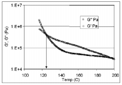 Figure 2. Parallel plate rheology data
for amorphous polystyrene
Figure 2. Parallel plate rheology data
for amorphous polystyrene
Other known problems with the determination of the solidification
transition exist, particularly in the case of immiscible blends.
DSC analysis shows every transition that occurs but has no means
of telling us which transition is significant. For example, a PCPBT
blend may show DSC transitions at 220°C for PBT and 140°C
for PC. However, blends with small quantities of PBT continue to
flow below 220°C, albeit at a higher viscosity. Hence, the DSC
based transition temperature has no means to tell us whether we
should choose 220°C or 140°C. A no-flow temperature, on
the other hand, would be able to distinguish the relevant transition.
Solutions
The parallel plate rheometer presents the means to accurately quantify
the solidification transition for all materials. It yields the temperature
sensitivity of viscosity at low temperatures, which increases model
accuracy. For amorphous materials, if the current noflow temperature
is indeed of importance for simulation, the G?-G? crossover, measured
by
the parallel plate rheometer, provides a quantified measure of the
solidification transition and sets a better stage for the correct
accumulation of residual stresses in the part, as the plastic moves
from the melt to the solid state. Further, the melt is in a state
of oscillatory deformation rather than the quiescent state seen
in the capillary rheometer. For blends, the parallel plate rheometer
will determine the significant transition. Further, it will yield
valuable information about the
change in viscosity with temperature across the transitions. The
DSC can be used for semi-crystalline materials. It remains a valuable
tool for shifting transitions, to account for effects of high cooling
rate.
Conclusion
A solidification transition is vital to good simulations. It governs
the change over from melt to solid state. Techniques exist today
to provide robust measurements of the no-flow temperature. Proper
implementation of these techniques will enhance the accuracy of
molding simulations.
SIMCON joins TAP
DatapointLabs announces the participation of SIMCON in its TestPaks
®
Alliance Program (TAP). CADMOULD is an injection molding simulation
program produced by SIMCON, a German software company with an international
client base in Europe, USA and Asia. TestPaks for CADMOULD are now
available at www.datapointlabs.com. CADMOULD users can now obtain
material characterizations for basic filling and post filling simulations.
DatapointLabs will provide support for warpage simulations on a
case-by-case basis.
National Research Council, Canada CAE codes
to be supported
Following an agreement with the NRC, the National Research Council
of Canada, DatapointLabs is developing TestPaks
® for users of PlasView,
BlowView and FormView.
TestPaks
® for PlasView will permit users to obtain input material
properties for filling, post-filling and warpage injection molding
simulations using PlasView. BlowView and FormView, blow molding
and thermoforming simulation codes, require visco-elastic material
models. TestPaks
® for these programs will provide the necessary material
characterizations to permit the simulation of these processes.
Simulation for twin screw extrusion supported
TestPaks
® are now available for TXS, a simulation program for fully
intermeshing co-rotating twin screw extruders. According to software
vendor Polytec, TXS can simulate a range of compounding operations,
and supports a variety of screw elements.
Two Testpaks
® have been developed by DatapointLabs. One, recommended
for amorphous polymers which are rubbery at ambient temperature,
contains all the properties required for simulations using the 'Melt
Only' option. The General TestPak is able to handle the simulations
for most other materials.
Additional details for these Testpaks
®, including specific tests
performed, are available at www.datapointlabs.com.
Keep your profile up to date
DatapointLabs.com is your window on our testing laboratory. Use
our site to view our test capabilties, read and download newsletters,
place orders and keep tabs on the progress of your work. View past
orders so you can easily find jobs that you have had performed in
the past.
Keeping your profile up to date permits us to process your orders
easily and efficiently, ensuring seamless flow of test results to
you.
If you do not yet have full access to our website, please contact
us for activation. A user name and password are required to place
orders on line.
